
stm32f030 devboard with TCXO
I'm interested in making a high accuracy real time clock (RTC). To experiment with the hardware I need for that, I created a development board based on the STM32F030F4P6 (which is a 20-TSSOP package) and a TCXO.
I chose that STM32 for two reasons: one, because it's cheap I can buy extras in case I screw things up. Two, it's a small package that I find easy to work with. My overall goal was to keep the costs under $10/board. They ended up costing $7.02/board.
I started with this devboard: https://hackaday.io/project/4277-stm32f030f4p6-breakout-board
It doesn't have a crystal so I added that. The resulting schematic ended up being:
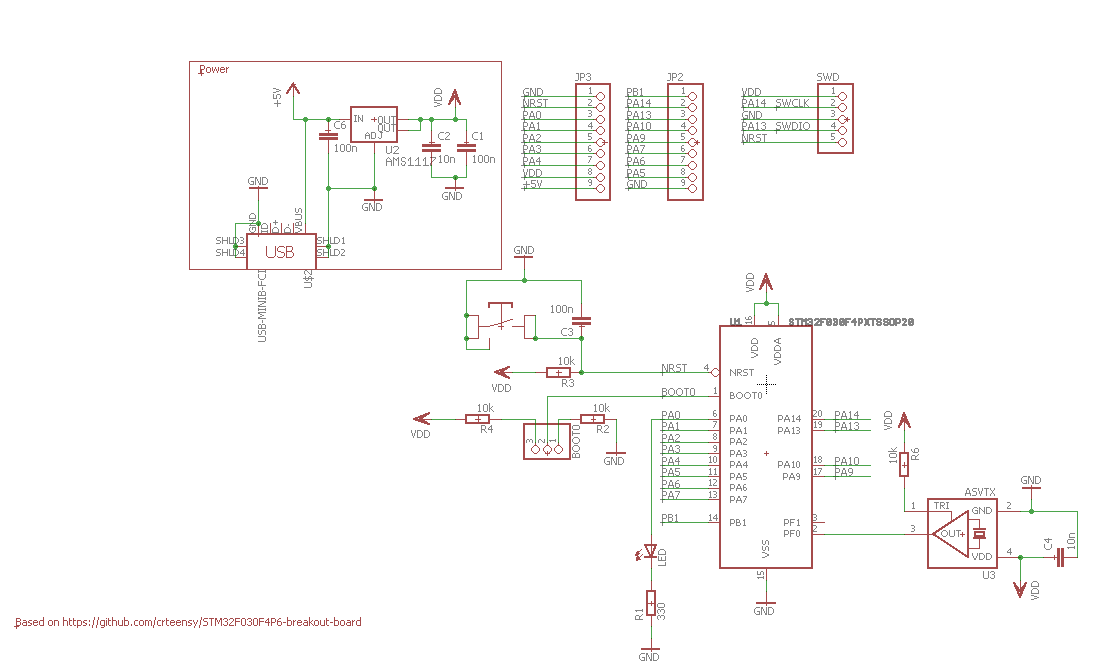
I had originally chosen the wrong TCXO, an ASVTX-11 which has a 0.8V peak to peak output. Thankfully, Abracon has models with the same pads with a HCMOS output. I ended up using an ASTX-H11. The ASTX-H11's output is a full 3.3V peak to peak, which works for me.
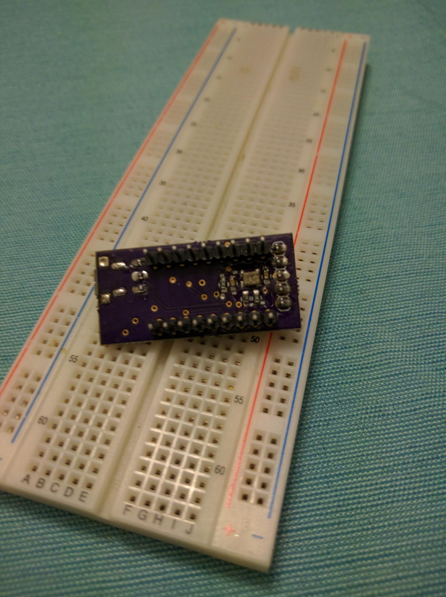
This is what it looks like assembled:
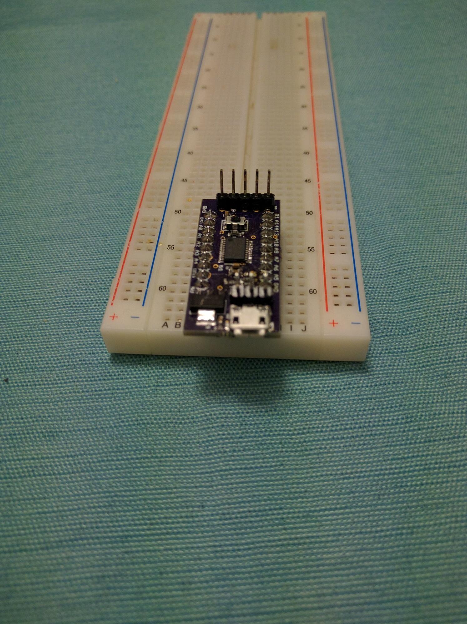
I had never soldered 0603 parts before, and they were challenging. I'm much more comfortable with larger parts.
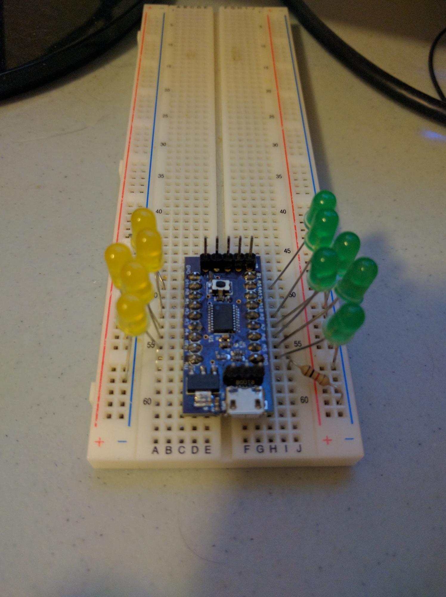
I setup a simple LED test to verify all the microcontroller pins were connected. After fixing a few pins, all LEDs were blinking.
There's a space on the board for a SMD LED, but the Eagle part I used must be bad because the solder mask is covering the pads for the LED.
Next test is to connect a GPS PPS to an input capture pin and measure the frequency of the TCXO.
I used stm32CubeMX to setup the pins, and my code looks like this:
/* USER CODE BEGIN Includes */
#include <string.h>
#include <stdlib.h>
/* USER CODE END Includes */

/* USER CODE BEGIN 0 */
void write_uart_s(const char *s) {
  HAL_UART_Transmit(&huart1, (uint8_t *)s, strlen(s), 500);
}

void write_uart_u(uint32_t i) {
  char buffer[12];
  utoa(i, buffer, 10);
  write_uart_s(buffer);
}

volatile uint32_t ms_at_irq = 0;
void HAL_TIM_IC_CaptureCallback(TIM_HandleTypeDef *htim) {
  ms_at_irq = HAL_GetTick();
}
/* USER CODE END 0 */
int main(void) {
  /* USER CODE BEGIN 1 */
  uint32_t last_ms = 0;
  /* USER CODE END 1 */
...
  /* USER CODE BEGIN 2 */
  HAL_TIM_Base_Start(&htim3);
  HAL_TIM_IC_Start_IT(&htim3, TIM_CHANNEL_4);
  /* USER CODE END 2 */
...
  while (1)  {
  /* USER CODE BEGIN 3 */
    while(last_ms == ms_at_irq) {
    }
    last_ms = ms_at_irq;
    write_uart_u(ms_at_irq);
    write_uart_s(" ");
    write_uart_u(HAL_TIM_ReadCapturedValue(&htim3, TIM_CHANNEL_4));
    write_uart_s("\n");
  }
  /* USER CODE END 3 */
}
This gives me two timestamps per GPS PPS: one in milliseconds from the systick timer (HAL_GetTick) and one in 48MHz cycles from timer TIM3. TIM3 is only 16 bit, so it wraps over 732 times per second. So I'm using the millisecond count to figure out how exactly how many times TIM3 wrapped. Using both together, I have a measurement precision of 20.8 nanoseconds. The serial output looks like this:
361682 11303
362682 38921
363682 1002
364682 28620
365682 56238
366682 18320
367682 45937
368682 8019
From that, you can see that each PPS is exactly 1000 milliseconds apart (which is what I was expecting, so that's good).
This is the math I used to measure exactly how many clock cycles happened between the first two PPSes:
# milliseconds ellapsed (+/- 2ms)
362682-361682 = 1000
# number of clock cycles @ 48000 cycles per 1ms
1000*48000 = 48000000
# number of 2^16 wraps in 1s
48000000/(2^16) = 732
# number of cycles in wraps
732 * (2^16) = 47972352
# number of cycles outside of wraps
38921-11303 = 27618
# total cycles
47972352+27618 = 47999970
# frequency error in ppm
(47999970-48000000)/48 = -0.625
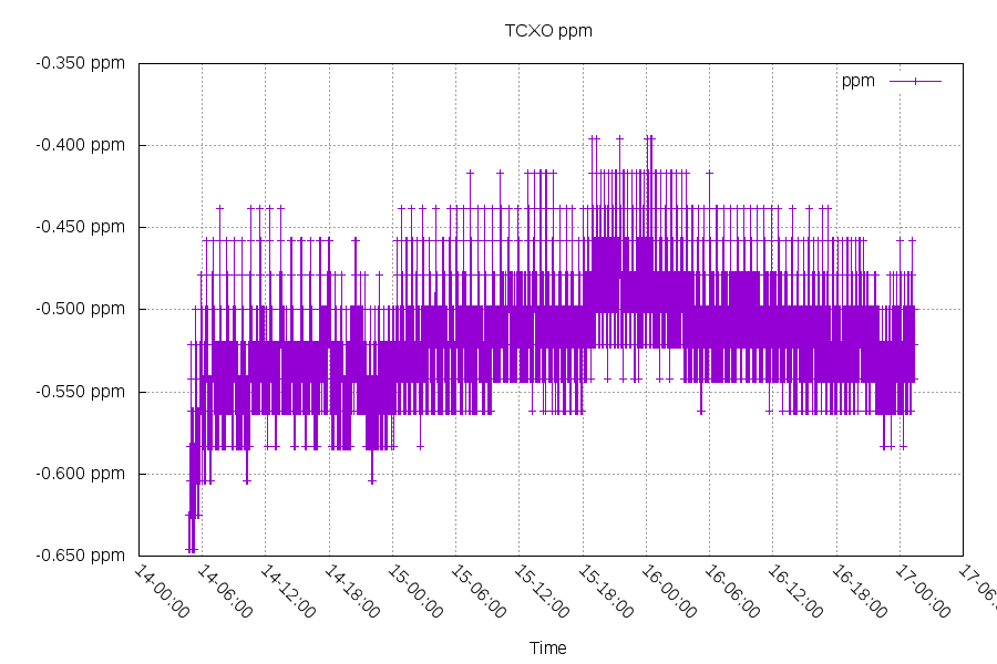
-0.625ppm is a reasonable result for this TCXO. The model I'm using claims +/-2.5ppm over -30C to +75C.
To verify that number, I can use the millisecond counter:
1273681 34332
...
2960680 32386
You can see it slipped 1ms in 2960680-1273681 = 1,686,999 milliseconds. This is -1/1686999 = -0.000000592 or -0.592 ppm. This is a reasonable result.
Applying this to roughly 3 days worth of data:
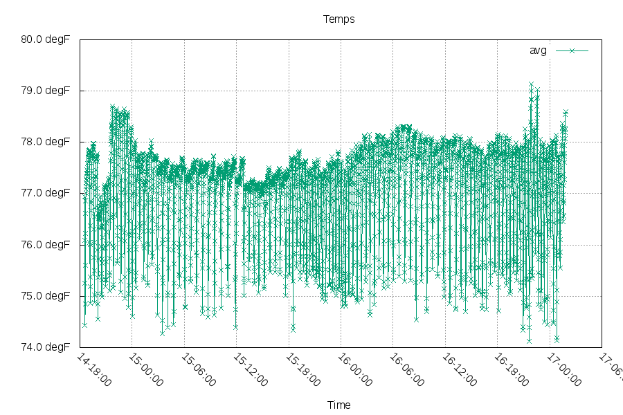
The temperature of the room looked like this:
So if I apply a +0.520ppm adjustment (+25 clock cycles per second), the time offset of this RTC looks like this:
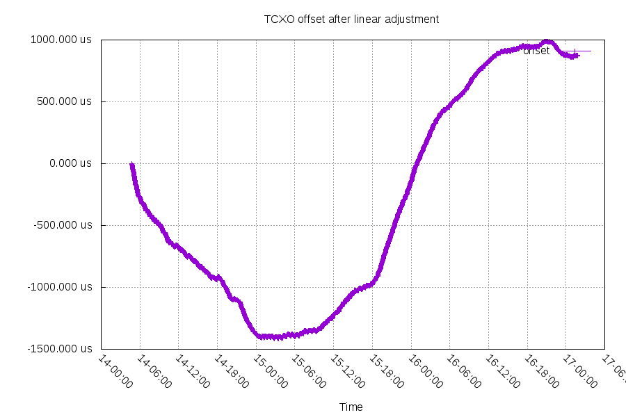
This is roughly 1ms/6 hours at the quickest change, which is 0.046ppm. My use for this RTC doesn't involve a GPS time source, so it will probably be worse as it ages and otherwise drifts. But it's still pretty good.
My next steps for this project is to generate a PPS and create an I2C interface for a Raspberry PI or other SBC to talk to.
Questions? Comments? Contact information