TCXO + Beaglebone Black, part 2
Starting from the previous TCXO modification, I wanted to get a 24MHz TCXO working.
Trial #1
I bought a set of three undocumented 24MHz TCXO's off ebay for $6. I was hoping that since they were not SMD parts, they would be easier to work with.
I used a decoupling cap and gave the signal a DC offset. I think TCLKIN is considered an "other LVCMOS pin", which needs Vmax over 2V and Vmin under 0.8V to properly trigger the BBB's edge detection. Below are all the measurements from the scope after the DC offset but without the BBB connected or any other load.
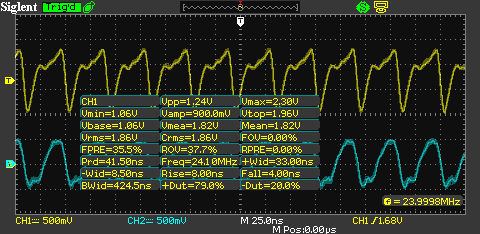
The main stats from this are Vmin=1.06V and Vmax=2.30V. The frequency counter has it at 200Hz under 24MHz (around 8ppm slow). Connecting this clock to TCLKIN didn't work, the counter didn't increment. Playing with the DC offset didn't help and I suspect that the crystal couldn't handle the current draw of the BBB.
Trial #2
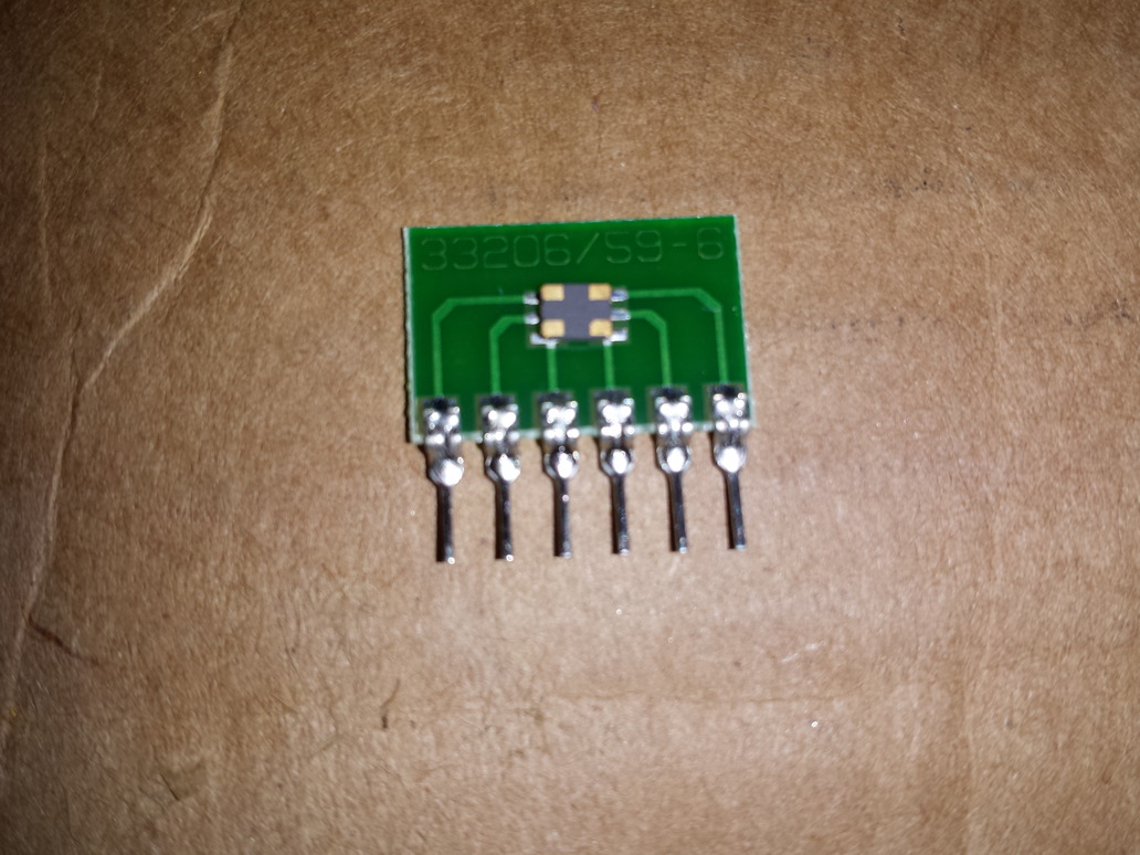
Next up, I tried my hand at SMD soldering. I cheated and used an adapter board to make experimenting easier. I couldn't find an adapter board for the exact crystal pads, so I made do with this 6 pin version. It turned out to fit very well. Below is a picture before soldering, with the TCXO upside-down to show the pads.
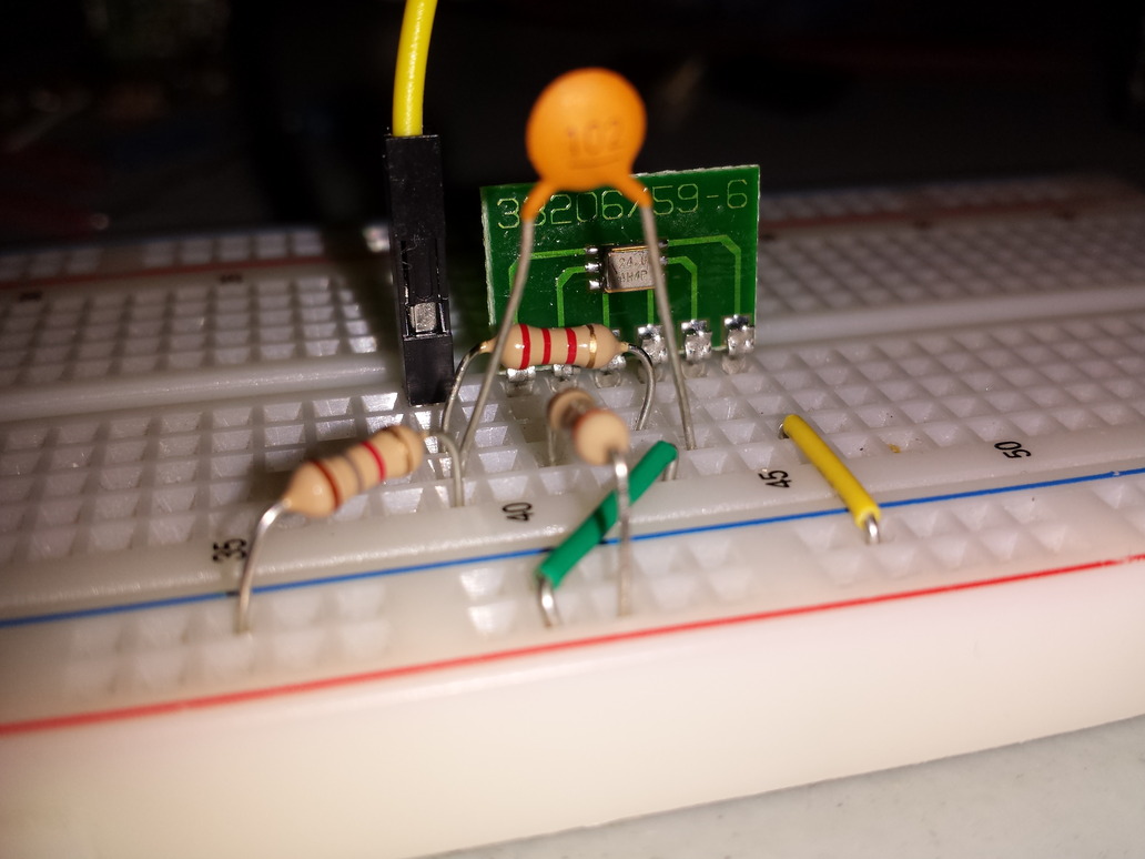
And next, on a breadboard (I know 24MHz on a breadboard is just asking for problems) with a decoupling cap and DC offset resistor divider.
The signal after DC offset:
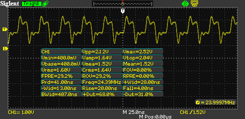
The main points are: Vmax=2.52V, Vmin=400mV, and freq=23.9997MHz. This frequency is slightly worse, 300Hz (~12.5ppm) slower than it should be. But the voltages should work.
Attaching this clock to the TCLKIN pin worked! Below is 15 seconds worth of data:
16 seconds of raw data:
counter delta between PPS
23999727
23999727
23999727
23999728
23999727
23999727
23999727
23999727
23999727
23999728
23999727
23999727
23999727
23999728
23999727
23999727
This is around 11.367ppm slow. Not very impressive for a TCXO that's supposed to be around +/-2.5ppm. I suspect this is my fault when I applied too much heat for too long trying to solder it in as I had trouble. I guess this means my scope's hardware frequency counter is accurate to around 100Hz, which is somewhat surprising to me.
Leaving it running as the system clock for a few days showed it wasn't doing very well:
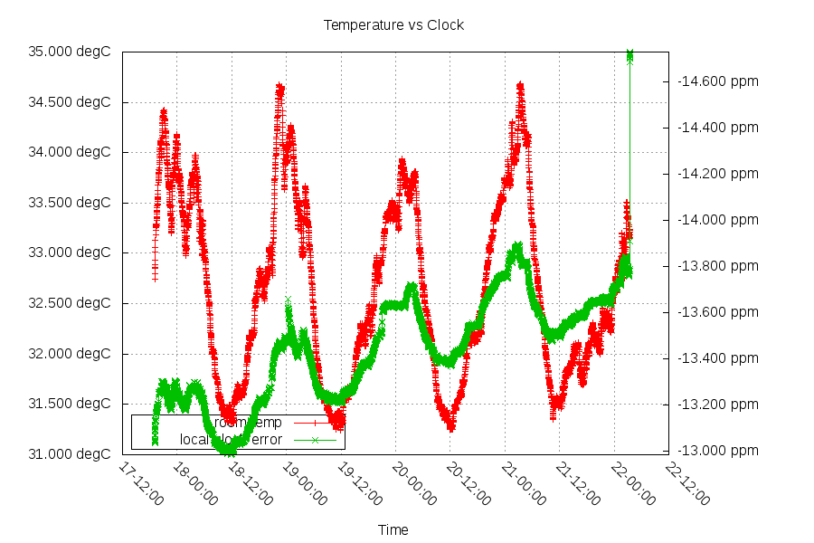
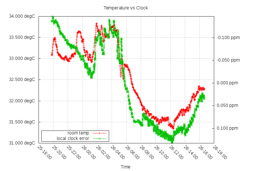
There's significantly more temperature based movement on this graph than there should be, and it looks like there's around 200ppb/day aging going on, which can't be a good thing.
Looking at the power supply, I see this noise on the Enable Output pin:
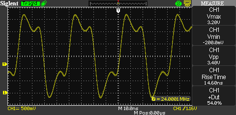
This noise shouldn't be here, and oddly the Enable Output pin is drawing 7mA and the Vdd pin is drawing 1mA. This TCXO is supposed to still work with the Enable Output pin floating, but mine doesn't. I'm going to write this off as "I broke it".
Trial #3
I went back to my "ebay special" TCXO's. I had seen this project use a PLL's comparator as a way to amplify and buffer a clock's output. I got a TI CD74HC4046AE IC to test this out.

This circuit got me the output below. The blue signal(CH2) is the input and the yellow signal(CH1) is the output. Note that the output voltage scale is more than twice as large.
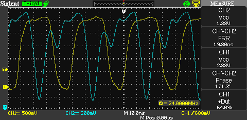
Not only did it amplify, but it also filtered the higher harmonics (48MHz, 72MHz, ...) in the input signal. Below is the just the output signal. Removing the probe from the input signal changed the output.
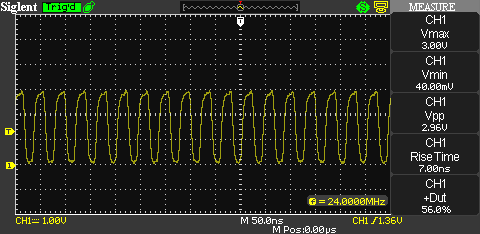
This is pretty good - plenty of margin above and below the needed voltages. Also, there is a tiny potentiometer with a tiny screw on top of these TCXO's. All of my tiny screwdrivers are too big, but I found a toothpick that was small enough to turn it. I used that to tune it within 100Hz.
As a design note, the raw output of this IC looks like this:

This is actually much too strong for what I need, so I added a 220ohm resistor to limit the signal.
Results
After a day, it looks like it's around 100ppb/C. An improvement, but I think it can do better than this.
