
Sharp Wireless Weather Station, part 2
rtl_433
The rtl_433 project has support for decoding a bunch of different weather station devices. Unfortunately, it doesn't support this sharp device.
Turning on rtl_433 unknown signal analyzer (-A) gives me this:
Detected FSK package @ 2018-07-18 20:12:11
Analyzing pulses...
Total count: 152, width: 37332 (149.3 ms)
[details removed]
Level estimates [high, low]: 1375, 5
Frequency offsets [F1, F2]: -2106, -8954 (-8.0 kHz, -34.2 kHz)
Guessing modulation: No clue...
It detected FSK and the right transmission length. The frequency offsets also look correct - the RTL-SDR was tuned to 917.21MHz for this test, and the frequency offsets are relative to that. But it wasn't able to get any farther than that.
It would be nice if I can add support for this device to the rtl_433 project, so I'll have to come back to that.
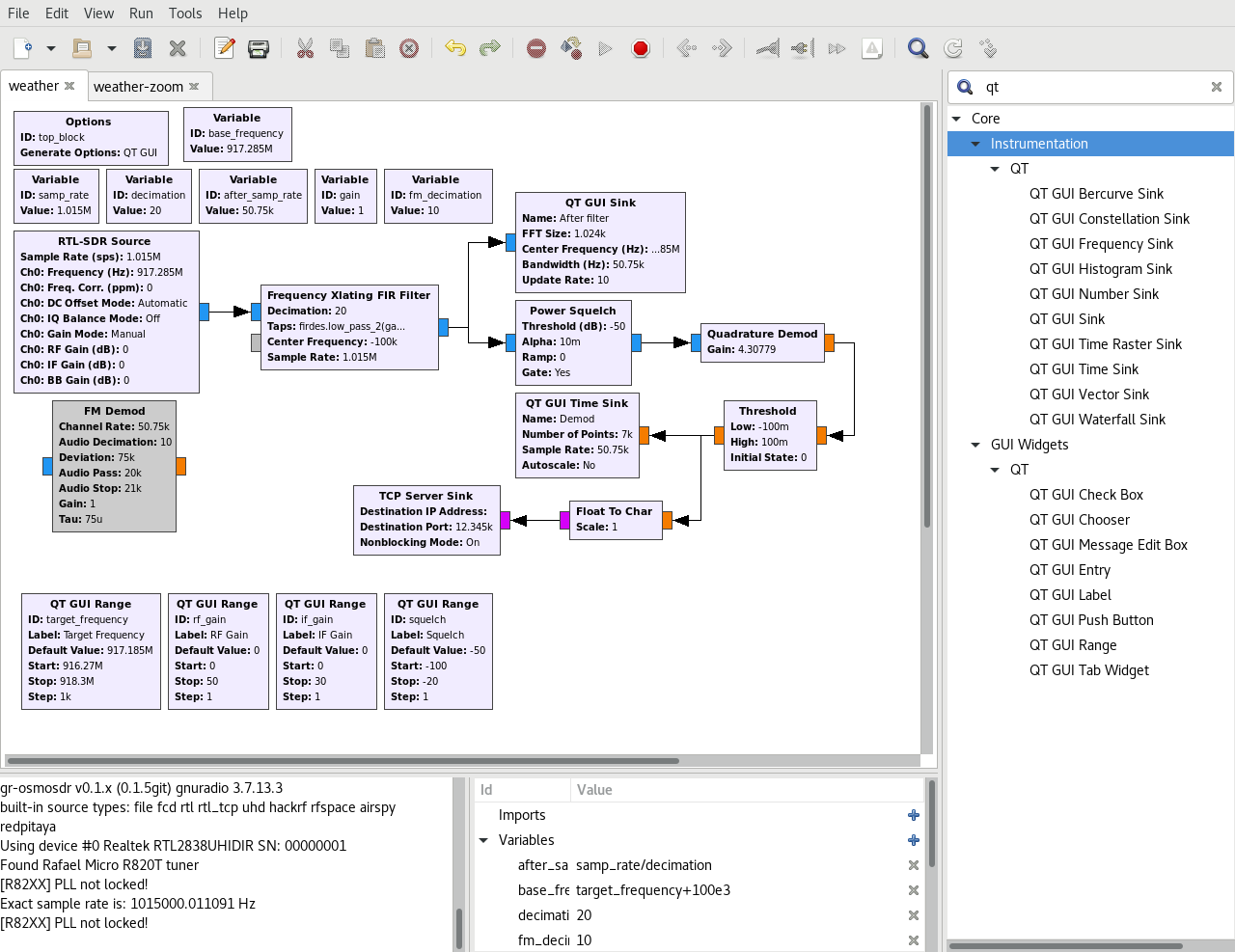
GNURadio
GNURadio is a handy DSP programming environment with a bunch of pre-made DSP modules you can connect together in input->output chains.
I took a look at other people's GNURadio FSK decoders, and found the quadrature demod module from them. It outputs a number relative to the received frequency. When it has a signal above the center frequency it outputs a number above 0, when the signal is below the center frequency it outputs a number below 0.
To set the center frequency, I used the Frequency Xlating FIR Filter before the quadrature demod block. I set the center frequency between the two transmitted frequencies.
I also added the Power Squelch block to only process the signal when it was above a configured signal strength threshold. That way, the processing is idle between transmits.
I added a threshold block to change the output to just 0 (low freq) and 1 (high freq). It uses hysteresis as a filter of some noise.
I wrote my protocol demodulation as a second process, and connected it to GNURadio using a tcp socket.
The full GNURadio flowgraph looks like this:
The GUI also has the ability to set the center frequency, the squelch threshold, and the RTL-SDR's gain.
Below the settings, the GUI shows the last 140ms of FSK output as well as a FFT on the RF. I've turned on the max hold of the FFT to see the transmission frequencies.
GNURadio running:
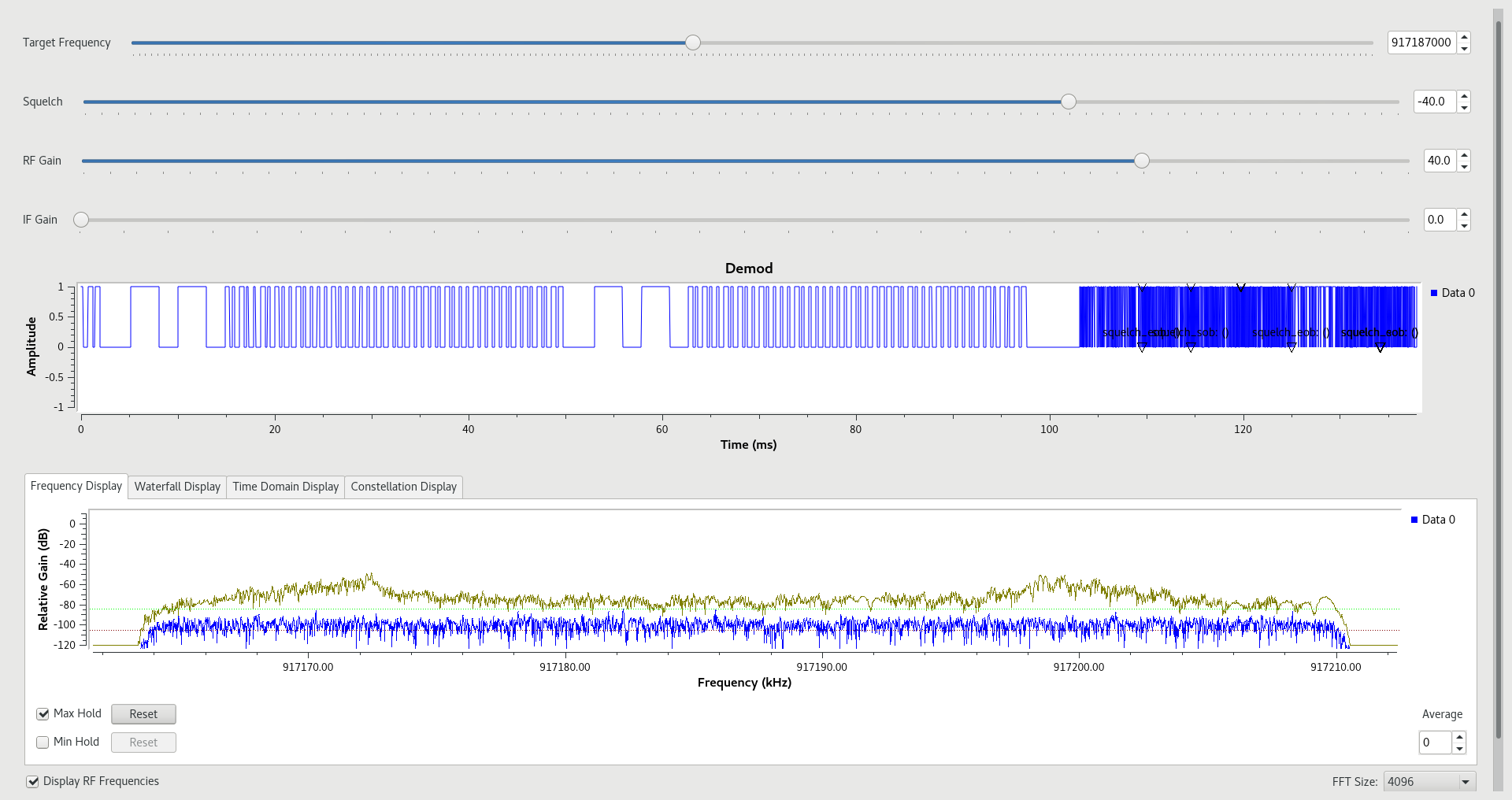
In the bottom FFT, you can see from the gold-colored line that the signal peaks at around 917.172MHz and 917.199MHz. You can also see that it's around 30-40dB above the current noise (in blue).
Above the FFT, in the "demod" section, you can see the data pretty clearly. There's about 0.6ms per bit (around 1700 bits per second, ignoring sync costs). There's also two different patterns, which looks like PWM encoding. To decode the data, I took the signal being high a long time + low a short time to mean 1 and high short+low long to mean 0. So the data in this transmission would be 101001010010000100000001001111010001111101101011
Decoding the signal
I collected a bunch of these signals and compared them against what temperature and humidity the receiver station displayed.
The meaning of the bits in the order they were received:
10100101 - seems to be a static data prefix
00100001 - seems to be an ID that changes whenever the batteries are changed
0 - battery state (0 = "batteries low", 1 = "batteries good")
000 - unused 3 bits?
000100111101 - 12 bits of temperature in fixed signed precision tenths of a degree Celsius (31.7C - it's cooling off at night)
00011111 - humidity in percentage (31%)
01101011 - crc
Signal Redundancy
My current guess is the crc is based on a Hamming code. Hamming codes are useful because you can use it to correct single bit errors. I've made some progress in reverse engineering it, but not everything is fitting exactly as I would expect. I'll have to work more on this.
Each transmission is repeated three times with the same data, so that's a useful error correction without knowing the crc.
Results and graphs
See part 3