
TCXO RTC Hats: Initial data
The TCXO RTC hats are collecting data. I'm focusing on the RTC part in this post. See also: other stratum 2 posts
Required picture
This hat is on an Odroid C2.
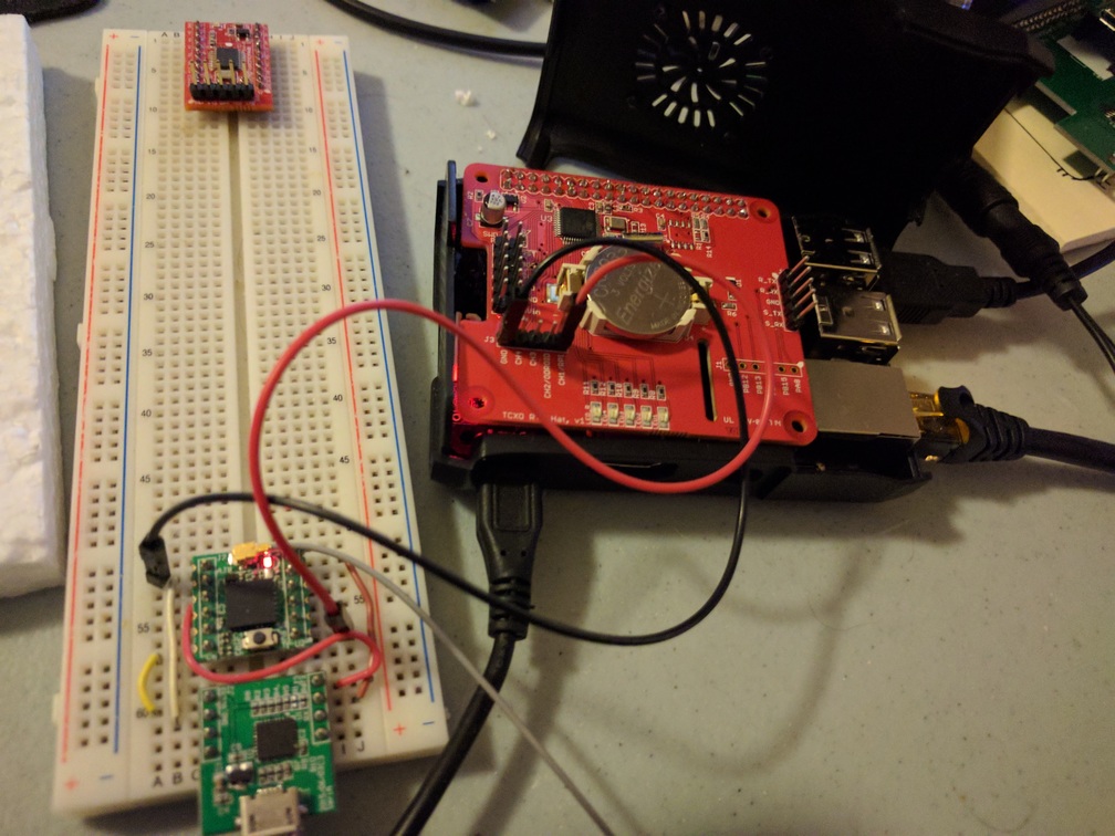
The GPS module on the breadboard (a Navspark Mini) is connected via the red wire to feed its PPS into the hat's channel 1. Channels 2-4 are currently unused.
data on the TCXO
The frequency measurements from the GPS PPS are compared with the temperature measurements to get the graph below:
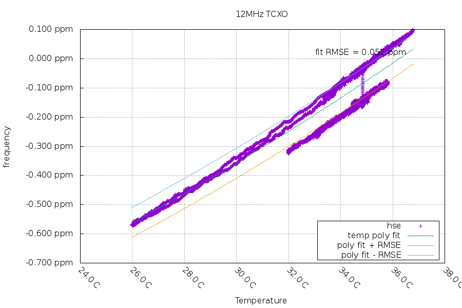
The crystal "jumped" in frequency and made this a less than good fit. The new line of data is parallel to the old line of data. I've seen this sort of behavior on new systems and it usually stops (or it happens with a smaller change). I'll give it a few days to see if it jumps again. If it stays without jumps for a week or so, I'll use that data as the calibration for this TCXO.
background on RTCs
Most RTCs used by Linux only have 1 second resolution. The work-around in place to get better resolution is for hwclock to poll the RTC's seconds digit until it changes. I want to do better than that for my RTC.
The RTC hardware in this stm32f031 is already better:
- Time resolution is in units of 1/1024 seconds (about 1ms)
- The RTC's exact time can be shifted forwards/backwards in units of 1/1024 seconds (roughly equivalent to adjtime)
- The RTC's exact frequency can be set in steps of 0.953ppm with a max positive correction of +488.281ppm and max negative correction of -487.327ppm (roughly equivalent to adjtimex)
So I'm just exporting those capabilities over i2c (simple client here).
My goal is to keep the RTC within 1ms of the system time. This will probably require adjusting the RTC every 15 minutes while the main system is on. Having the RTC in sync will lead to the system time having less error after a reboot or power off.
The RTC has its own (low power) 32kHz crystal. It only uses around 0.001 milliwatts of power compared to the main system's TCXO taking around 14 milliwatts, which leads to much longer coin cell battery lifetimes.
data on the RTC
Comparing the RTC's frequency with the PPS:
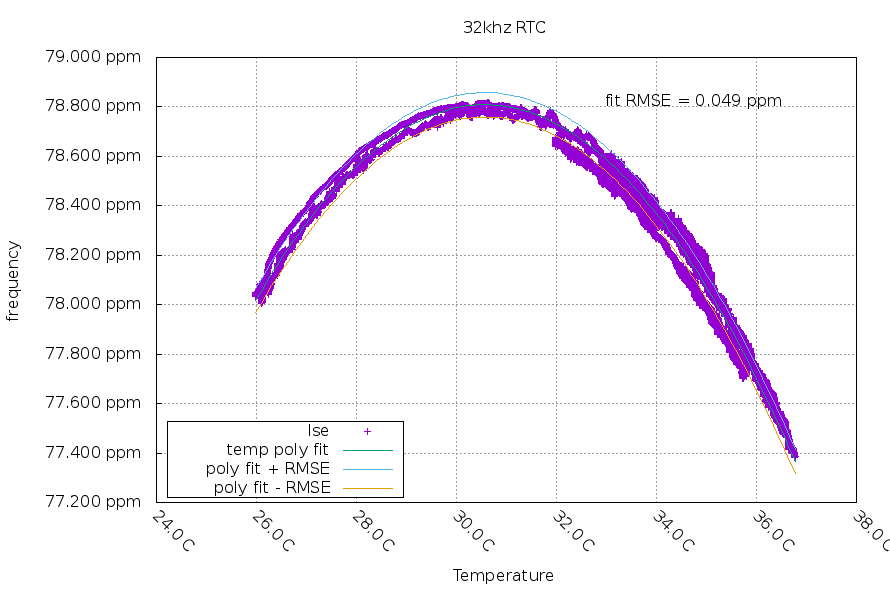
This looks like a typical crystal, and you can see a dramatic difference if you compare it to the TCXO graph (the TCXO has smaller changes when the temperature changes).
This graph matches very well with the RTC crystal's datasheet numbers:
| Spec | min | typical | maximum | actual | notes |
|---|---|---|---|---|---|
| Turnover Temperature | +20C | +25C | +30C | +30.5738C | measured temperature is on the microcontroller, it is expected to be warmer than the crystal |
| Frequency Coefficient (ppm/T^2) | -0.040 | -0.034 | -0.028 | -0.037551 | |
| Expected frequency error | -20ppm | +20ppm | +78.8086ppm | load capacitance error included in actual but not the other columns |
temp poly fit equation in graph: ppm = 78.8086 - 0.037551 * (x-30.5738)^2
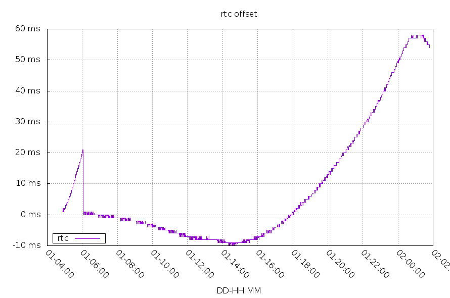
Below is the difference in time between the RTC and the Linux system. I haven't written the RTC sync program yet, but you can see that around 1ms precision should be possible. The sudden drop down at 01-06:03 GMT was me adjusting the RTC by hand.
RTC Power usage
The power usage by the RTC is almost beyond my multimeter's ability to measure at 0.5 microamps.
My first coin cell battery monitoring code left the measurement circuitry enabled all the time. This adds a 30 microamp constant load on the battery. I've adjusted the code to only turn on the circuitry when the battery is being measured. This averages out to around 0.2uAh/h of usage. The CR2032 battery has around 200mAh of total capacity, so this load should last many years.
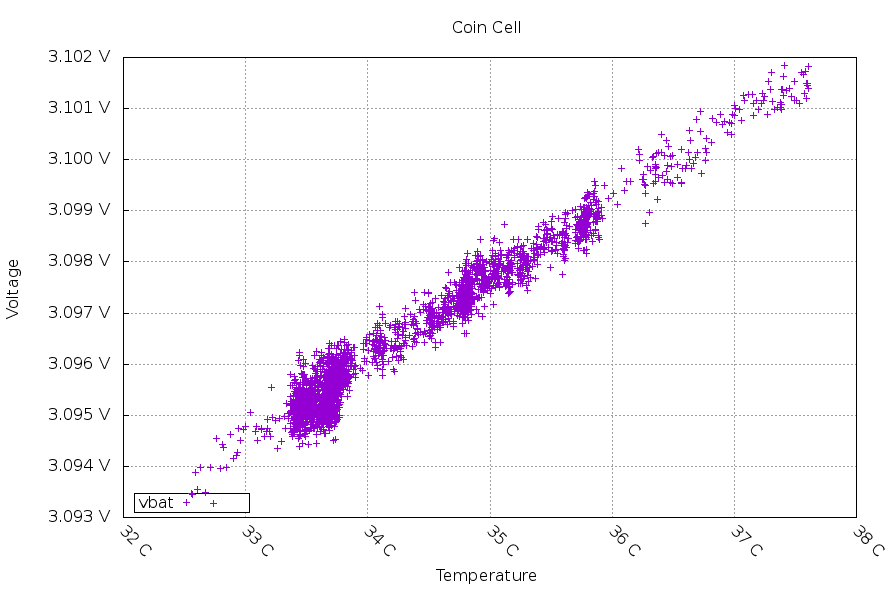
You can see most of the battery voltage change so far is probably due to temperature.
Code
The code to the stm32 controller and the Linux i2c clients are on github.
Questions? Comments? Contact information