
Embedded NTP client/NTP interleaved mode, part 3
Previous posts: part 1, part 2
In this post, I wrap up my embedded NTP client and use it to measure the difference between my other two NTP servers with hardware timestamps.
Goal 1: synchronize the local clock
Like my esp8266 project, this needed to parse the GPS serial data and accept a PPS. There's a delay between the PPS that marks the beginning of the second to the serial data from the GPS to tell you the full time and date.
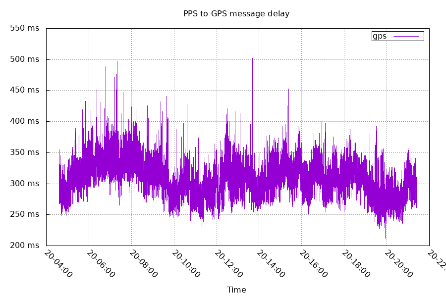
This delay from the GPS comes from the GPS waiting till it finishes processing the signal data before printing out the serial data.
I connected the GPS's PPS to timer 2's channel 4 (TIM2_CH4).
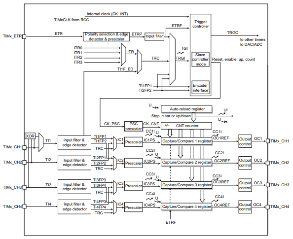
When a PPS happens, the timer copies the count (CNT) to the capture register. I can use this data to synchronize the local clock to the GPS clock. Like before, I used a PID controller.
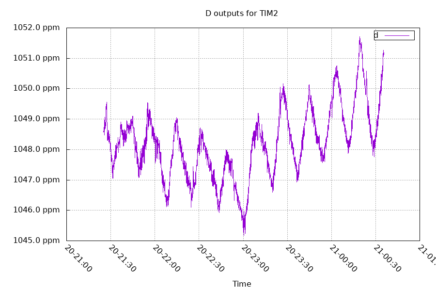
The majority of the controlling happens from a linear least squares estimation providing the "D" in PID. This hardware has an inaccurate clock that moves a lot due to temperature changes. But we can still work with that.
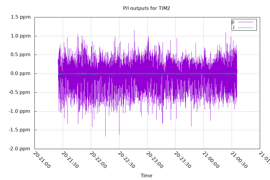
The P and I terms correct the remaining error. I have the P constant set higher than usual because of both how precise the measurements are, and how quickly the crystal changes frequency. This trades a lower offset for frequency stability.
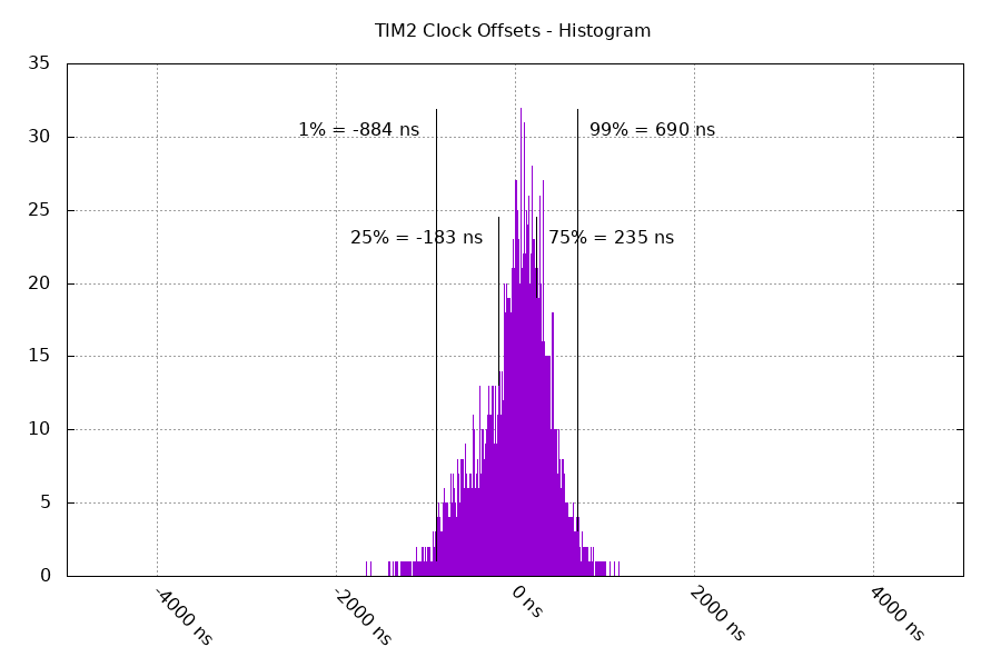
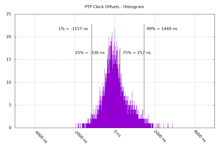
This results in a decent synchronization between the local clock "TIM2" and the GPS clock. The histogram below has the offsets after sync.
Goal 2: Synchronize the NIC's clock
The NIC has a separate clock used for PTP/IEEE1588 hardware timestamps.
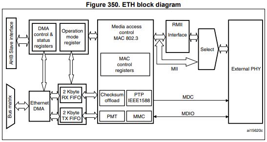
This is a 63 bit counter, with the upper 32 bits representing the seconds and the lower 31 bits representing the fractional seconds. The lower 31 bits can either be in nanoseconds (overflow at 1 billion) or in binary fraction (overflow at 231). Because NTP timestamps are 232 binary fraction, a simple bitshift makes it easy to convert the latter mode.
To control the frequency of the counter, I'm using the "fine correction" mode.
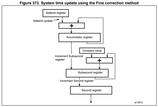
This uses the addend+accumulator to divide the system frequency by a fractional number, and it adds a constant value to the subsecond register every time the accumulator overflows.
The accumulator overflows every 232 seconds, and the subsecond overflows every 231 seconds. The rate at which the second updates is:
(addend * systemFreq) / 232 * updateConstant / 231
The systemFreq for this hardware is 168MHz. So for this hardware, the default values I'm using are:
(4223155695*168000000) / 232 * 13/231 = 1.000000000111 seconds/second
This is 111 parts per trillion fast, but that's close enough for my purpose. This also results in the clock granularity being 13/231 seconds, or 6ns. The addend being a 32 bit value makes the frequency control have very precise steps (about 200 parts per trillion per +/-1 step).
In order to compare the time that's in the PTP clock with the system time in the TIM2 clock, I'm using the connection between the two:
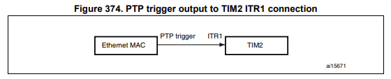
If you scroll up to the timer block diagram, you can see the ITR1 signal at the top. I set this up to route ITR1 to TRC, and then connected TRC to TIM2_CH1. I then set the PTP clock to trigger that signal at a precise PTP timestamp, and timer 2 captures the local timestamp in channel 1's capture register. From that data, I can find the offset between the PTP and TIM2 clocks.
I then take the offsets, feed it to a PID controller, and synchronize the two. Because both the PTP clock and the TIM2 clock are derived from the same crystal, I'm using TIM2's linear least squares estimation as the D term for the PTP clock.
Below is the sync between the PTP and TIM2 clocks.
Goal 3: measure clock offset with other NTP servers
Other servers:
I've disabled the NTP RX timestamp adjustments on chrony. This puts the timestamp of the NTP packet at the PTP point between the ethernet SFD and ethernet header (instead of the end of the NTP packet). This lowers the measured round trip time by 720ns. The archmax is using timestamps at the PTP point as well. Because this is symmetrical for my setup, it does not contribute to asymmetric delay, which would result in an offset.
On the datasheet for the Archmax's PHY, RX buffering for RMII reclocking should take 38 bits or 380ns. This should result in a 190ns offset.
I'm using interleaved NTP with hardware timestamps on both RX and TX on both the clients and the servers. The network is a simple generic 8 port 10/100/1000 ethernet switch.
Final results: Offset between NTP servers
Offset between cheese/archmax:
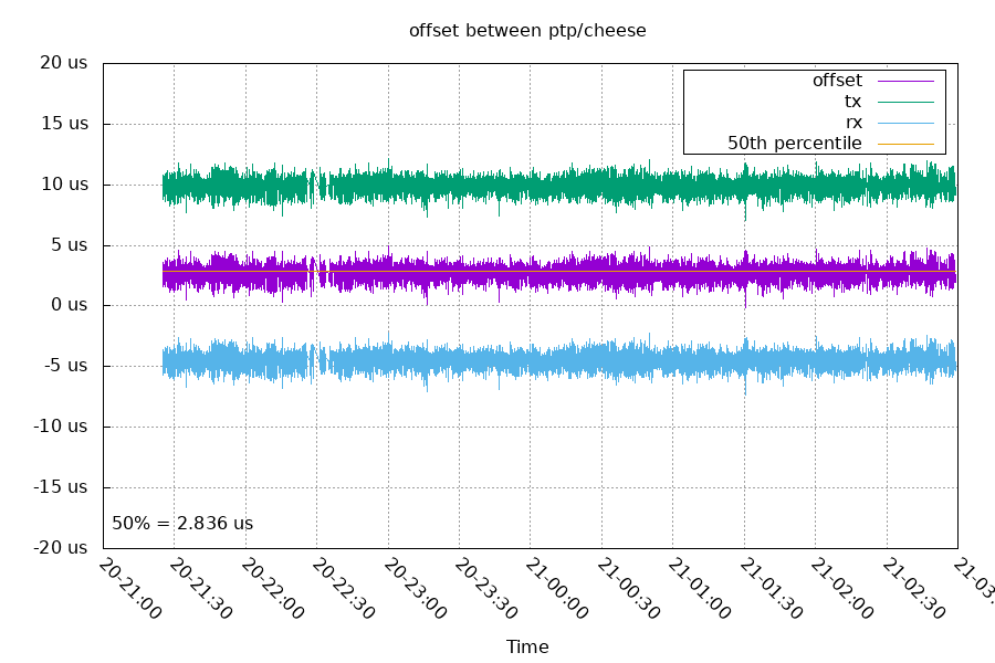
This is a round trip time (excluding processing time on the NTP server) of 15 microseconds. There's an unexplained static 2836 ns offset.
Offset between stm32mp1/archmax:
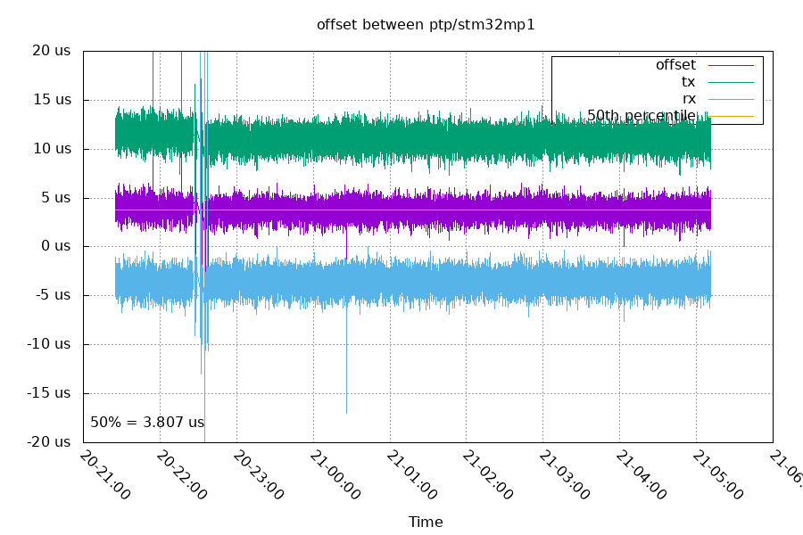
At 22:37, I restarted chrony a few times on stm32mp1 to reconfigure it to exclude RX timestamp adjusting. The TX and RX are from the perspective of the archmax, so we would expect the archmax TX (stm32mp1 RX) set to move. You can see the RX samples are a straight line, but the TX samples have moved closer to the RX samples. Comparing the medians of the RTTs before and after, it reduced by 711ns. This is pretty close to the expected 720ns.
The median offset after the change was 3779 ns. This is 943 ns higher than the archmax/cheese pair.
Offset between cheese/stm32mp1:
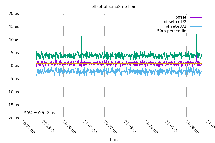
These are both gigabit, so they have a quicker round trip time. They also see an offset between the two clocks of 942 ns. This is pretty close to the 943 ns difference between the two that the ArchMax measured.
This graph starts after the RX timestamp change and has a median RTT of 5999ns. Before the change, the median RTT was 6732ns, a change of 733ns. That's also very close to the expected 720ns.
Code for this project is on github
Future Plans
Next, I want to:
- add a NTP server mode to the ArchMax
- use interleaved mode for the server
- port to a Teensy 4.1
- use an external TCXO as TIM2's timebase
Questions? Comments? Contact information