
binary clock
I've been working on a clock that gets its time from the internet and has a binary display. It should use NTP to keep its clock within tens of milliseconds of true time. It should automatically adjust for daylight savings time. It should keep an estimate of the local clock's error and slew time instead of stepping it. Hardware is an esp8266 nodemcu v1 with a SPI ST7735 1.8" screen.
1: simple NTP client
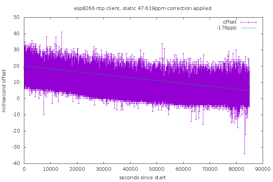
This got time from the internet. This is roughly 24 hours worth of data. The height of the purple offset bar is the round trip time to the NTP server. The local clock was manually set to a 47.619ppm error correction. The cyan line estimates the remaining error of around 0.176ppm.
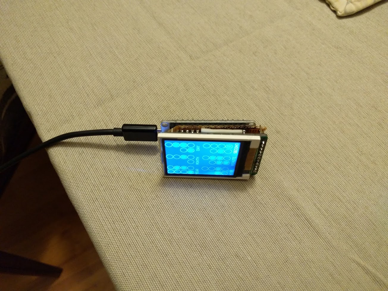
2: display
I attached the esp8266 to a SPI display and setup the graphics.
Here's a video of it: binary clock on breadboard
The video starts at Jan 17, 2016 02:59:49 - each field has two columns: the tens digit and the ones digit encoded in binary.
3: faster display
Originally I was using the Adafruit GFX primatives to draw to the screen, but that was slower than I wanted. I figured out how to convert images to raw bitmaps, store them in the esp8266's flash, and display them to the screen.
video showing random images - the uneven backlight is due to my trying to glue the screen down and used a little too much glue.
Filling the screen with 16x16 pixel icons, it can do around 45fps. video showing the value of millis() in binary.
4: fancier display
Since I have ~800kb of flash to work with (roughly 200kb of code and libraries), I figured it'd be nice to have different icons for different holidays. icons for birthday, halloween, independence day, thanksgiving, and valentines day. I added a few more icons after that video to a total of 13. These icons use 3,328 bytes of flash in total.
5: lose the breadboard
Next, I put new headers on the LCD board and soldered both the LCD board and the esp8266 to a piece of perfboard with some wire jumpers.
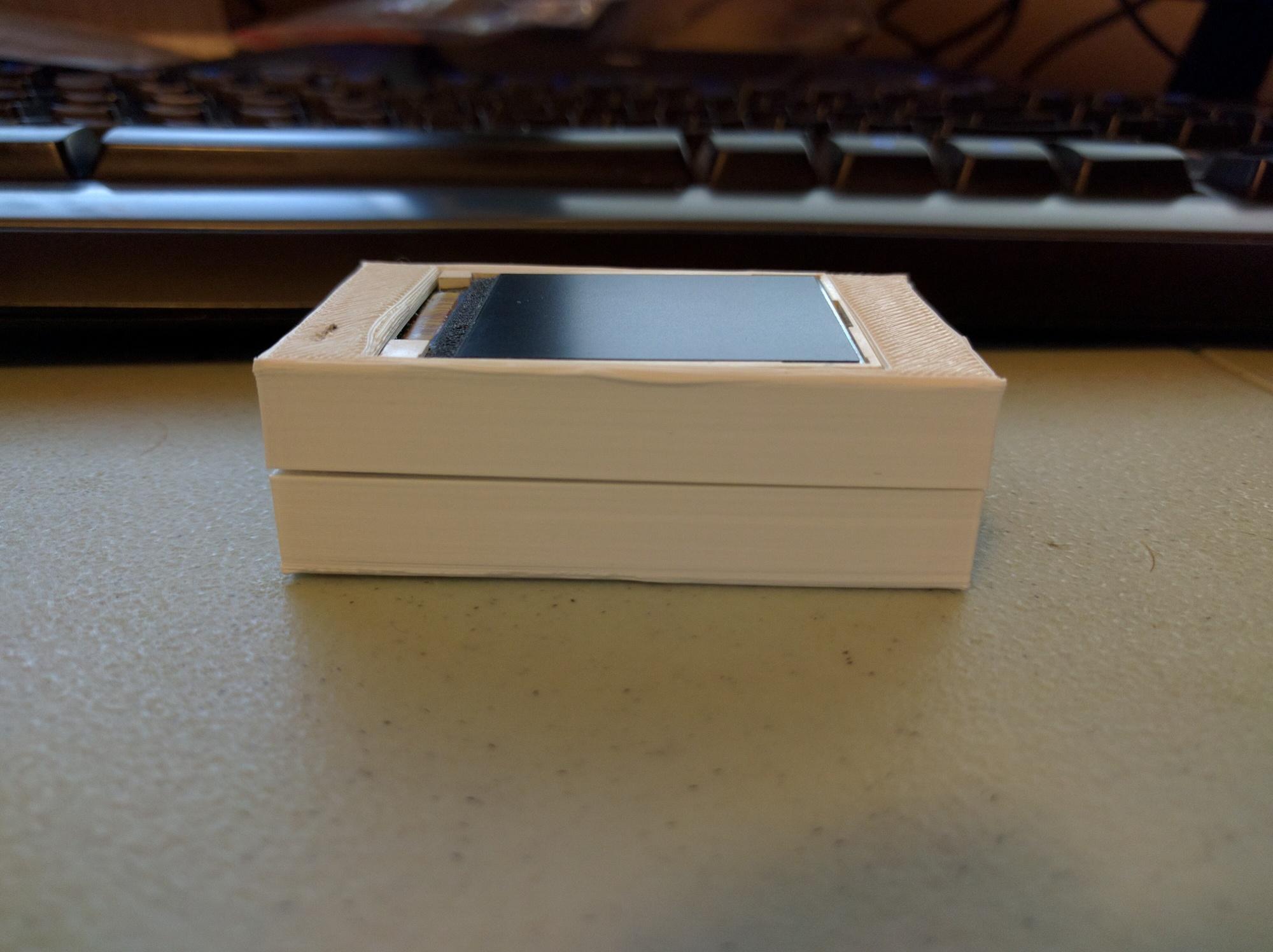
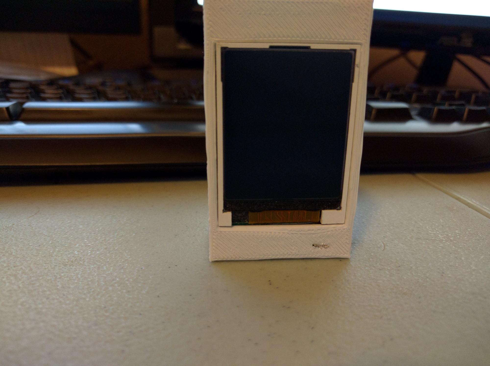
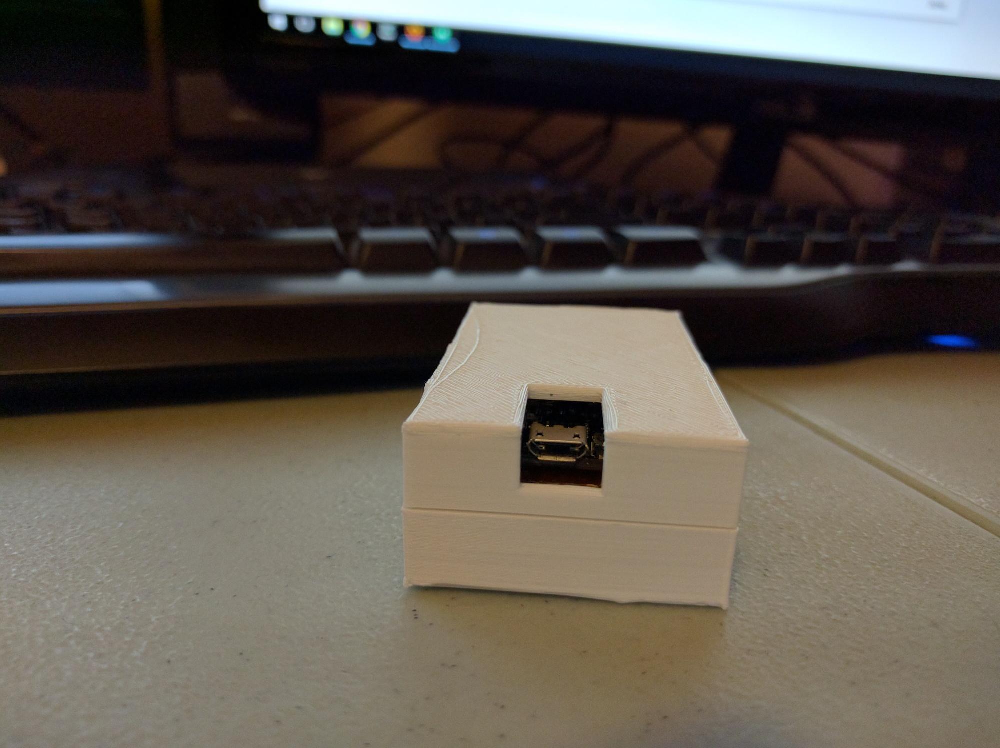
6: make a nice case
I designed a case and 3d printed it.
side:
front:
usb:
7: continue work
The case has a few problems: the USB opening is too small for the cable, the header pins under the display are slightly too tall and result in a ~1mm gap on the side, the mounting standoffs were too large and the friction fit between the two sides is a bit too snug (so it had to be sanded down to fit).
I have a few goals I want to do with the software too.
The code repo for the software is here.
See part two of this project.
Questions? Comments? Contact information