
PPS over USB
Goal
For keeping your system clock on time, you can't beat the Pulse Per Second (PPS) signals available from $10 GPS modules. They typically have better than 100 nanosecond accuracy. GPIO PPS is one of the best ways to get that timing information into your system, but the hardware needed to use a GPIO PPS is not available on every platform. USB is available on almost every server, but by itself adds unpredictable latency to PPS timing information. This project aims to measure and compensate for USB latency to make it a decent PPS timing source for servers that can't use GPIO PPS sources.
Diagram of USB PPS
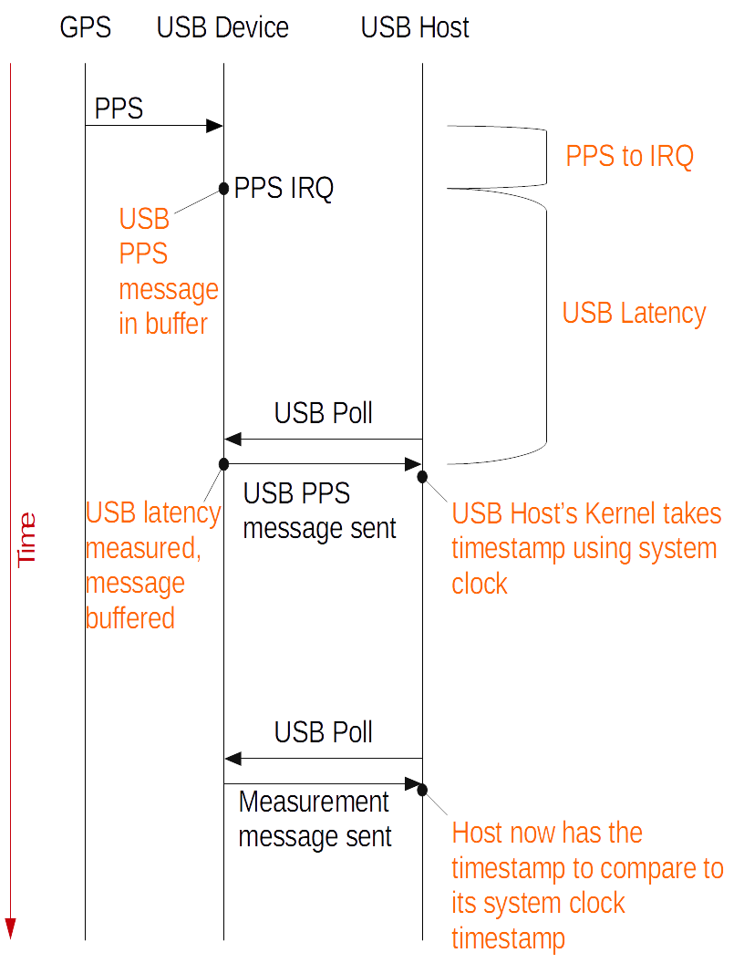
PPS to IRQ data
This is the top part in the diagram: the time between when the USB device gets the PPS and when its interrupt handler is run.
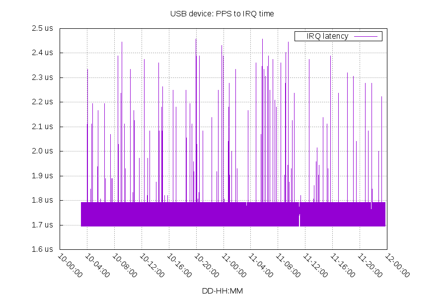
This ended up being around 1.7us-1.8us on the USB device. This will take longer on systems with a full operating system.
USB latency
This is the middle part of the diagram: the time between when the USB device buffers the PPS message and when the USB host picks it up on the next poll.
The USB Device's control interface bInterval is set to 1 (=1000us). This tells the USB host to poll the device's status every USB Frame. The majority of USB latency comes from this polling.
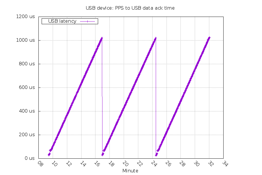
The USB latency varies from 26us-1033us. I'll go more into the triangle shaped pattern later.
Measurement message
The measurement message is a simple text message sent as regular UART data.
Putting all this data together
After the host gets the measurement message, it has all the info it needs to calculate the difference between its time and the GPS's time. This difference is also called the offset. Below is a graph comparing GPIO PPS and USB PPS time sources on a Raspberry Pi 2 system. In an ideal world, these would both be flat lines at 0. Things are not ideal however. The USB PPS has a ~125us static offset which is possibly from the USB hub buffering the data. Static offsets are easy to deal with, so I removed it for this graph. I also tested on an Intel system, and the USB PPS had the same static offset.
- The same PPS signal is connected to both the GPIO PPS and USB PPS
- GPIO PPS does not compensate for PPS to IRQ latency on the Pi 2 (expected values ~10us)
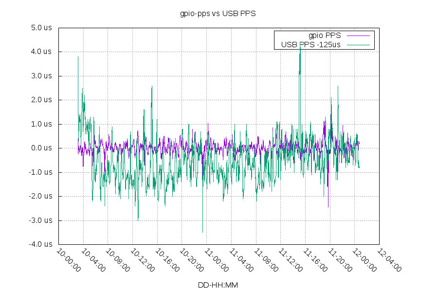
The USB PPS time source stayed within +/-5us, so it's good for long term frequency stability (wander). The USB PPS source has a lot steeper and longer changes compared to the GPIO PPS, which is bad for short term frequency stability (jitter).
Graphing this data as a histogram of offsets, I would expect it to look somewhat like a Gaussian distribution.
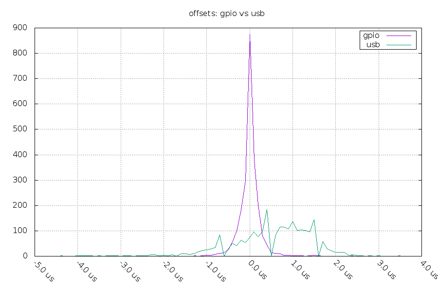
The GPIO PPS is much closer to this than the USB PPS. This is another way to measure short term frequency stability.
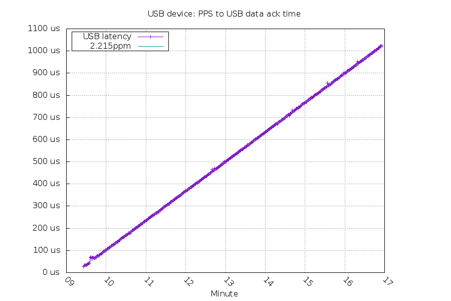
Extra: USB latency pattern
Looking closer at the USB latency, you can see the PPS drifting relative to the host schedule of polling the USB device for its status. The system clock error was 2.215ppm during this time period, and this drift matches that error exactly. This probably means USB on this system shares the same clock as the system clock. This hardware is a Raspberry Pi 2, and I suspect it won't be true for other platforms. I also suspect the stability of the polling schedule can't be relied upon, as the host controls it and can reschedule it whenever it wants.
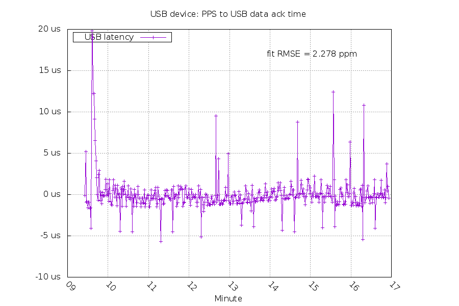
Subtracting the 2.215ppm drift gives the remaining jitter (root mean squared error=2.278).
Extra: a breakdown of the pieces needed
- Hardware: GPS module with PPS + STM32F103 devboard + Linux computer with USB
- Firmware for the STM32F103 devboard
- DCD/PPS signaling and USB message timestamping had to be added to the STM32's CDC middleware
- Linux kernel module - DCD signaling support had to be added to the Linux kernel's CDC driver
- Client to send timestamps to NTP via SHM
Extra: related posts
UART/USB bridge timing,
Old related USB PPS,
Older related project from 2013