
GPS module measurements
Starting point
I got a u-blox NEO-6M and I wanted to compare it to my NS-T. Since I don't have a frequency counter, I decided to try creating one myself.
The hardware I have on hand is a 72MHz STM32 devboard. I used the input capture hardware on the STM32 to measure the PPS timestamps from the two GPS modules. The timer on the devboard has a 13 nanosecond resolution. The devboard sends the difference in timestamps over USB serial to my logging and graphing program.
Hardware design follows the "wires going everywhere" style. I took over a corner of the dining room table to run my tests.
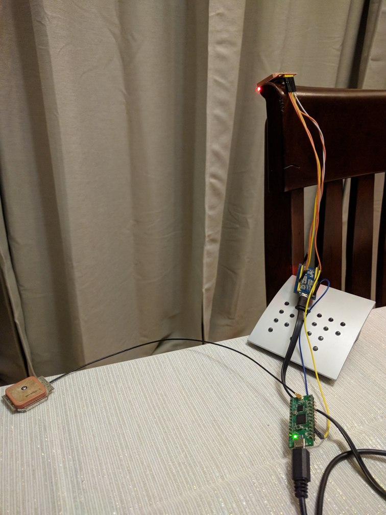
The NEO-6M's built-in antenna was ok, but I had trouble getting it to lock while indoors. Using an external antenna closer to the window helped a lot.
I gathered an hour and 15 minutes worth of data. The graph below is the difference in timestamps between the two GPS modules.
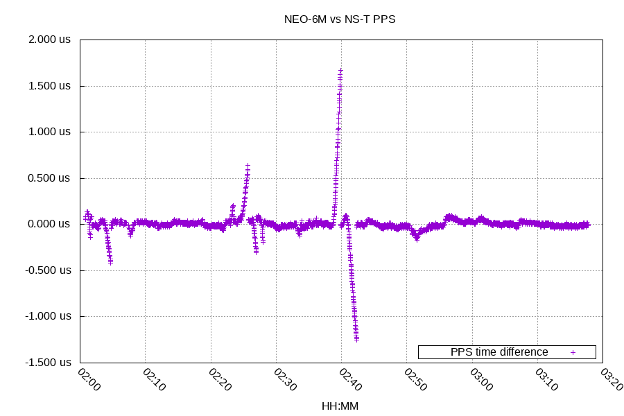
Ok, what was going on in that graph?
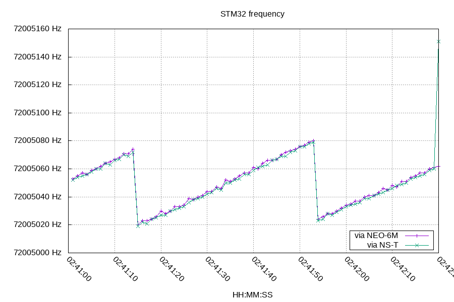
Taking a closer look at the drift between 02:41-02:42
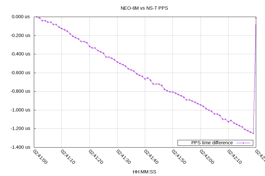
One of the modules drifts 1.2us off and then jumps back. The drift probably came from a temporary signal loss and is roughly 0.016 ppm off frequency.
Which GPS module was drifting off?
To answer that, a third clock is needed to compare the other two. This third clock is provided by the STM32 board. To make it easier to see, I've removed the 70ppm frequency error from the STM32's clock. I've started all three clocks at the same offset and let them free run from there.
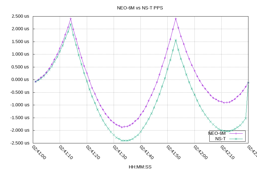
Since the NS-T clock jumped back to agree with the NEO-6M, it was most likely the one drifting. The NS-T was set to output PPS even without 3D lock, and it only had a lock part of the time of the test. The jump probably came from it re-acquiring GPS lock after having lost it for a minute. The NEO-6M had a better antenna for these tests, which is another factor.
Wait, why is the STM32's clock moving around so much?
It's moving around a lot more than I would have expected. So I investigated that next.
The major sources of error are: the external crystal changing frequency and the PLL changing frequency.
Before exploring these sources of error, I wanted to verify that the problem was actually with the STM32. Looking at the frequency of the STM32's clock as measured by the two PPS shows that both PPS agree that the STM32's clock has a sawtooth pattern.
Measuring the external crystal changing frequency
I disabled the PLL and ran the devboard off of just the 8MHz external crystal. Since USB on this board requires 48MHz or 72MHz, I used the uart instead of USB to log this data.
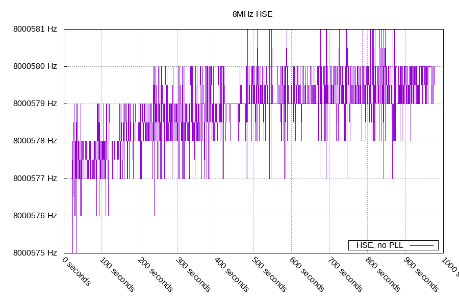
The external crystal (HSE) maximum frequency to minimum frequency was 6 Hz, which is 0.750ppm. It didn't really follow a sawtooth pattern. The gradual drift faster is probably from the crystal getting warmer.
Measuring the PLL changing frequency
I tried a few different PLL settings: 2x (16MHz), 4x (32MHz), 6x (48MHz), and 9x (72MHz). I also added two additional boards to the comparison. I removed the median offset of every frequency to just show the jitter. This animation is running at 5x normal speed.
Board 1 is this board, board 2 is a similar board with the same processor (STM32F103) and a slightly different design. Board 3 is a different processor in the same family (STM32F031) with a TCXO. You can see that the TCXO board is vastly better.
With the board 1 and board 2 PLL data, you can see the sawtooth pattern of slowly moving up until it jumps down quickly and starts slowly moving up again.
What about other options?
This processor also has an internal resistor/capacitor oscillator (HSI), let's compare that.
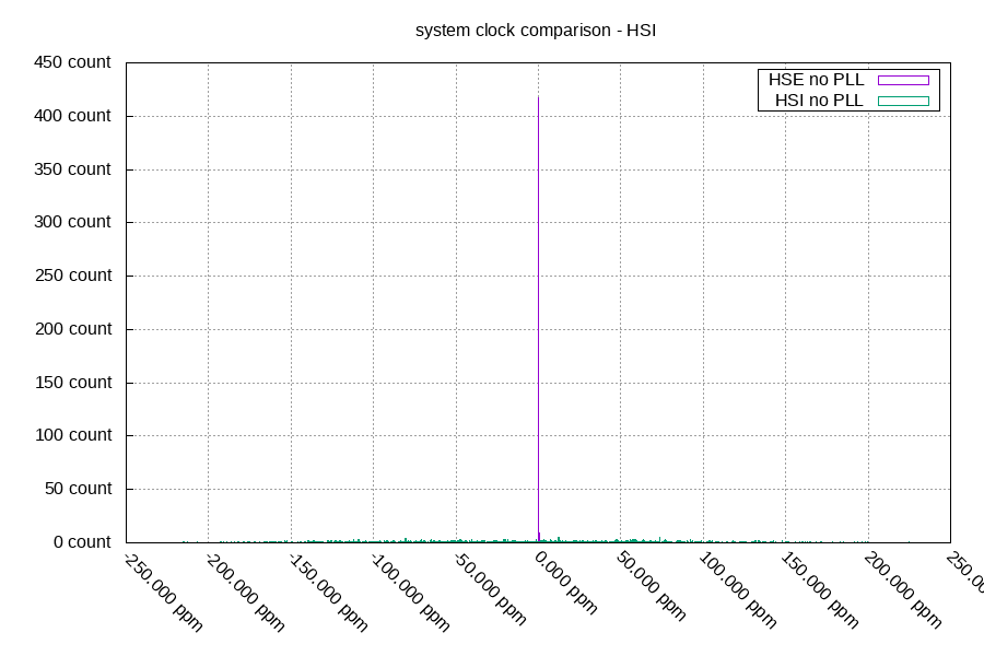
The HSI frequency was spread over a 400ppm max/min range which makes the 0.8ppm max/min range of the HSE look tiny by comparison.
Summary
The external crystal (or the crystal driving circuitry) on these boards moves around a lot in a short timeframe. The PLL makes that worse. This has changed my expectations for future projects. Using a TCXO helps significantly.
Doing a search for people running into the same thing, I found this: https://jaybee.cz/software/stm32-hse-oscillator-stability-problem/
Another report of the same level of noise (30Hz on 36MHz MCO vs OCXO): https://web.archive.org/web/20190316163517/http://stm32duino.com/viewtopic.php?f=19&t=3103
See part two