
Temperature compensation
Temperature effects are usually the largest source of frequency changes in clocks. So I have three temperature sensors on my test system.
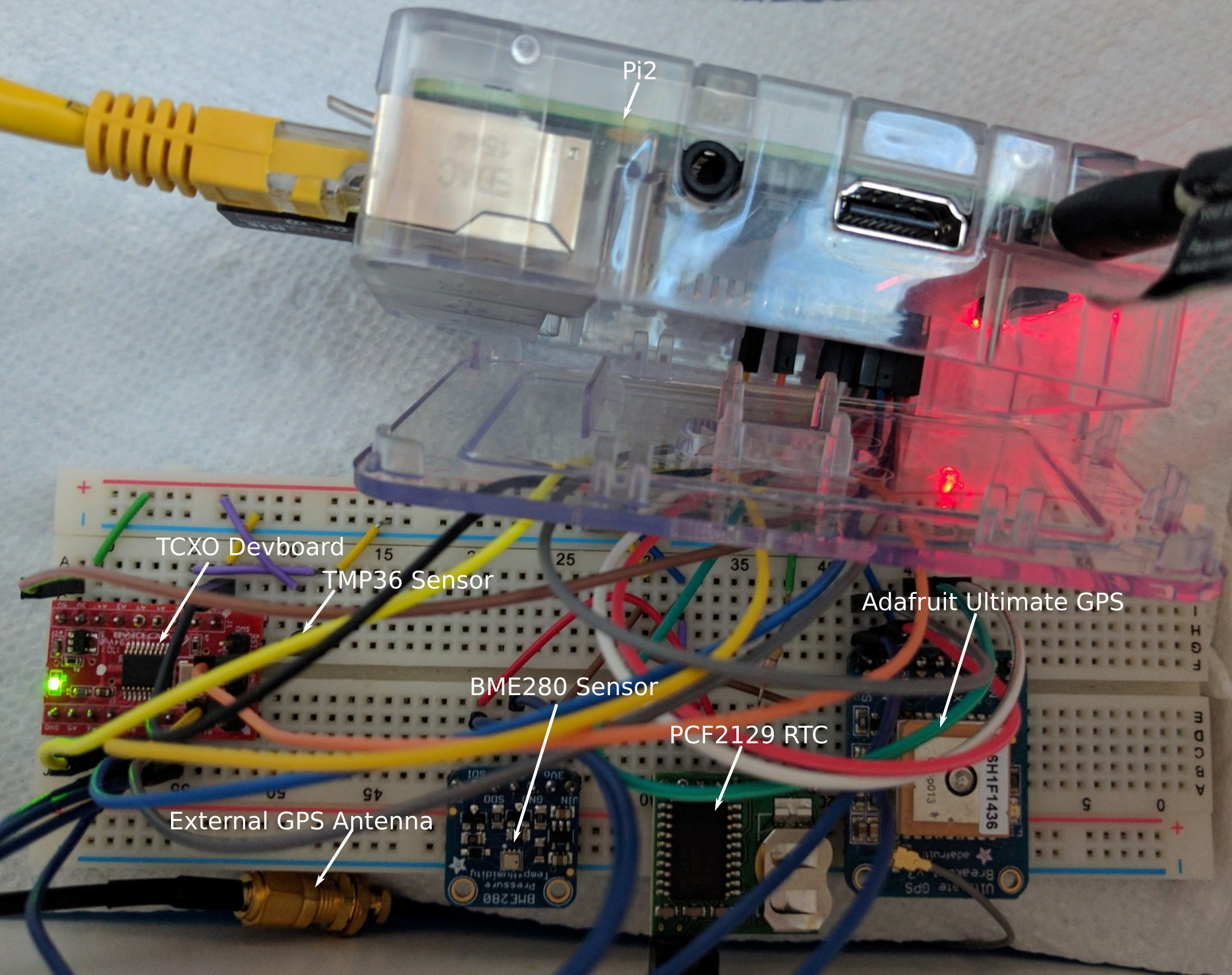
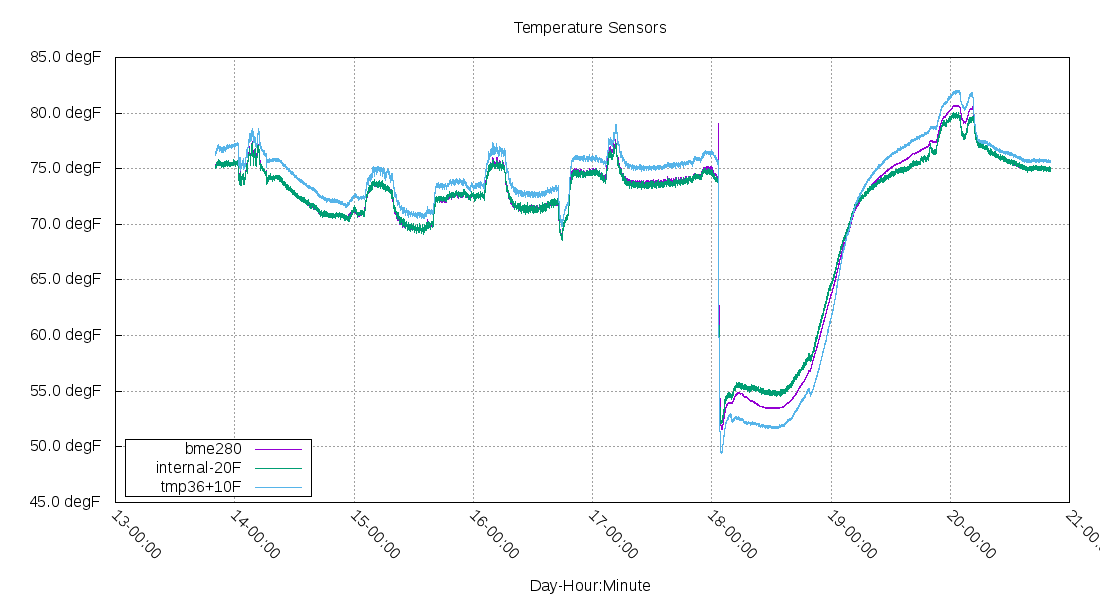
The sensors are: one built into the stm32 chip, a TMP36 sensor, and a BME280 sensor.
Comparing temperature sensors
The data has some static adjustment (stm32's internal was 20F high and the tmp36 was 10F low).
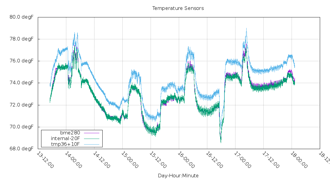
The relative movements in all of them track pretty well.
Voltage sensor
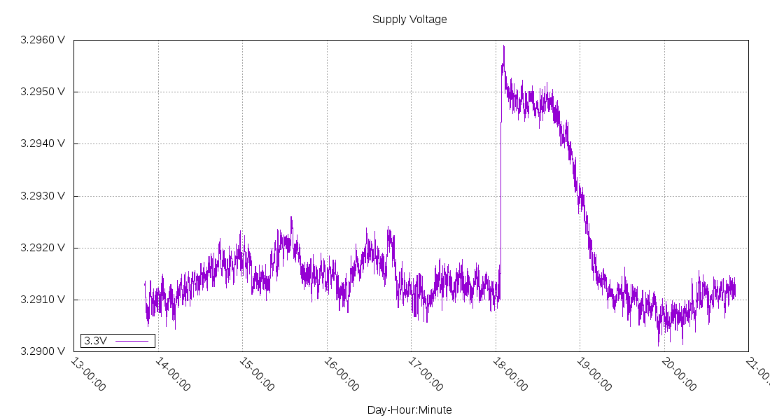
In order to tell the temperature from an analog signal, a measurement of the supply voltage is useful.
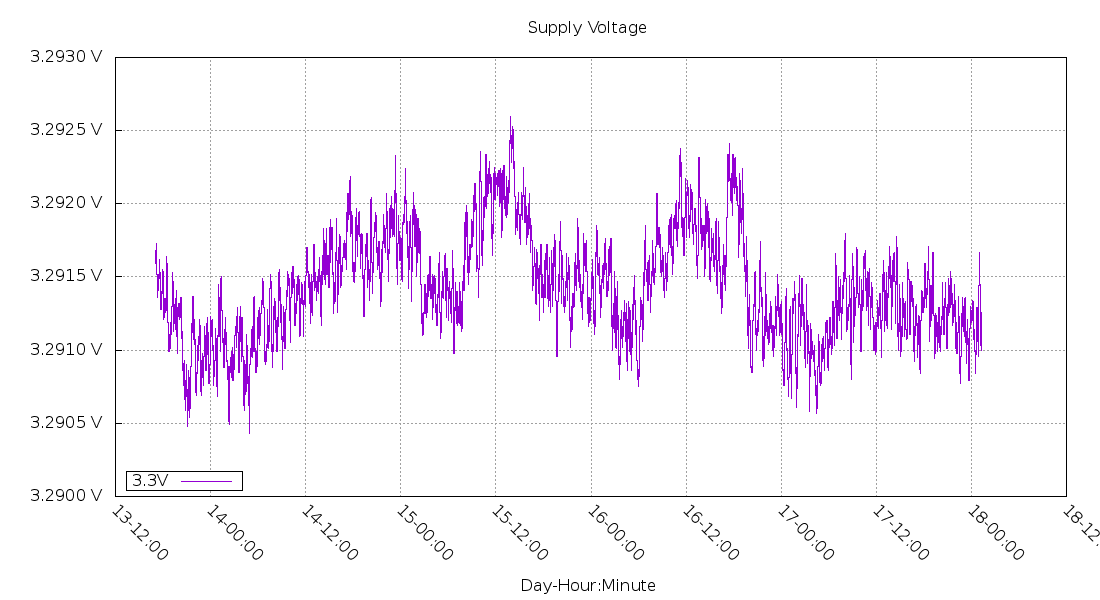
This is measured with the built-in voltage reference in the stm32. The data is pretty noisy, so I've averaged 10 minutes of data sampled at 10Hz. The datasheet for this stm32 model claims the reference is +/- 100ppm/degC and a 10mV voltage spread over -40C to +85C. I'm using the factory calibration values stored on the stm32f030's rom for both temperature and voltage.
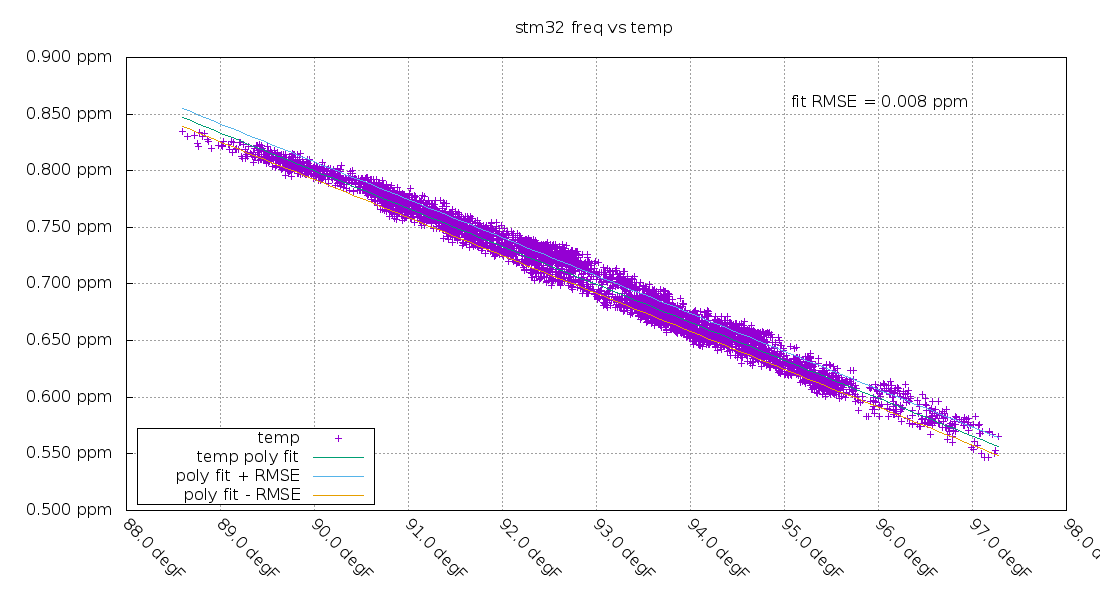
Temperature vs frequency
Next, I compared the frequency of the TCXO vs the stm32's internal temperature sensor. Of the three sensors, the internal one was the best fit. This is probably due to the internal sensor being directly connected to the TCXO via the same circuit board, while the other temperature sensors were further away. With the sensor and TCXO being directly connected, external temperature changes conduct between them easier. The root mean squared error (RMSE) of this linear fit is 8ppb!
Taking that linear fit and looking at the remaining error, to see if it changes over time:
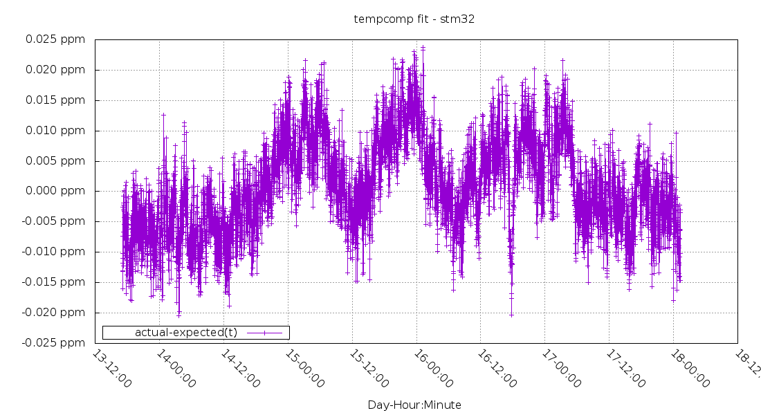
It drifts in a +/- 25ppb range, still a pretty good result.
The points aren't completely linear though, there's a small curve to the data.
Getting colder
To gather data on what happens at colder temperatures, I put the whole system in a cooler with an ice pack at the bottom.
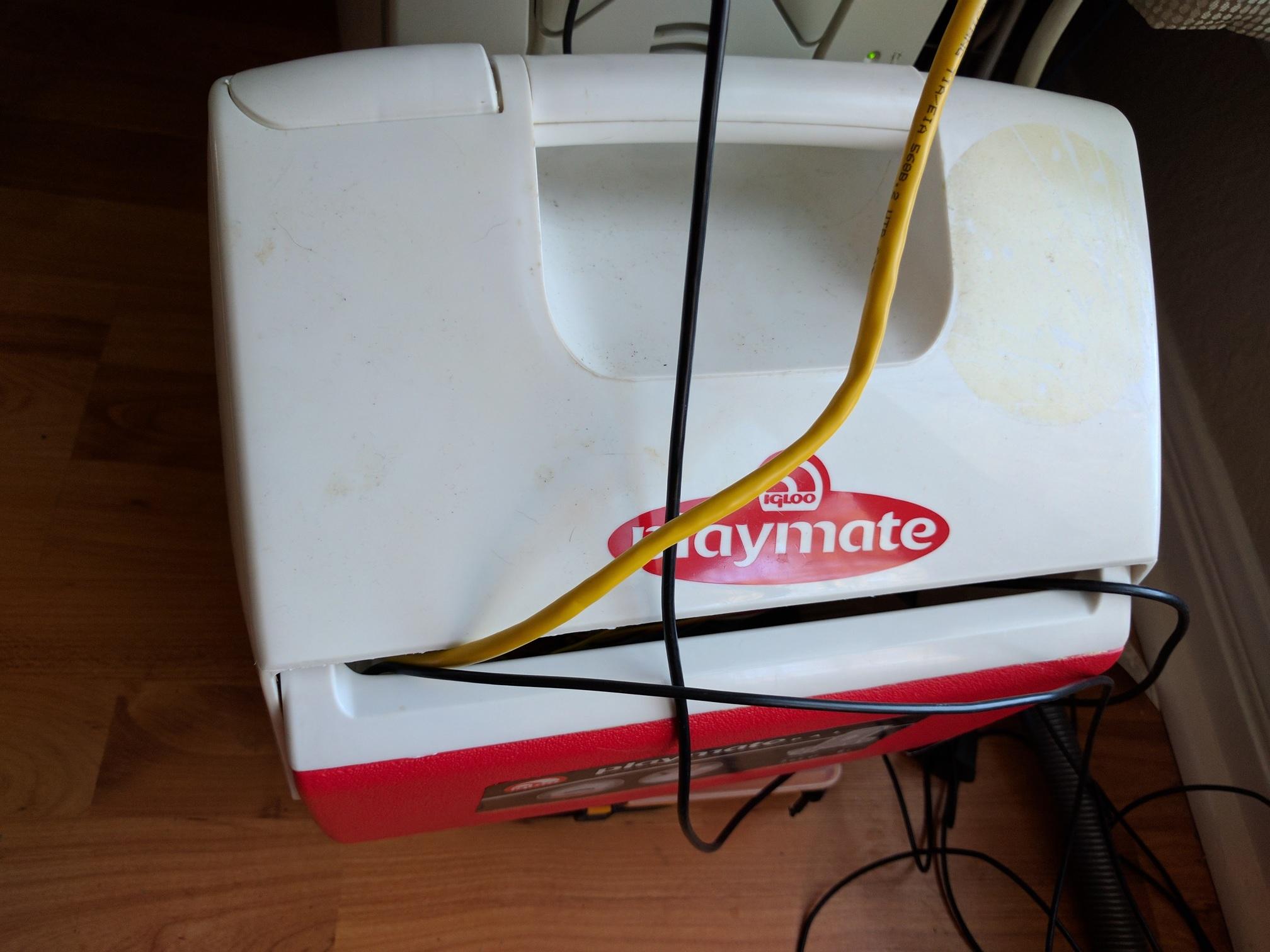
The temperature immediately dropped and is now slowly getting warmer.
The temperature change affected a bunch of other things.
The supply voltage shot up about 4mV:
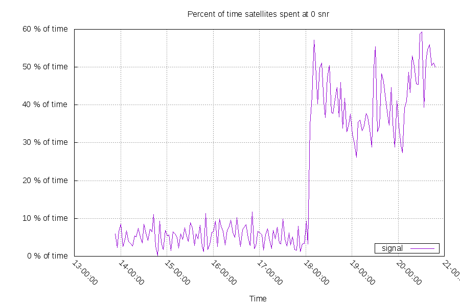
The GPS started having problems receiving the satellite signals. My first theory was it has an estimation of its local clock frequency, and the sudden temperature change affected that. The antenna is external, so it isn't a matter of the position of antenna changing or the cooler blocking the GPS signals. Moving the Raspberry Pi to be farther away from the GPS module seems to have raised the SNR.
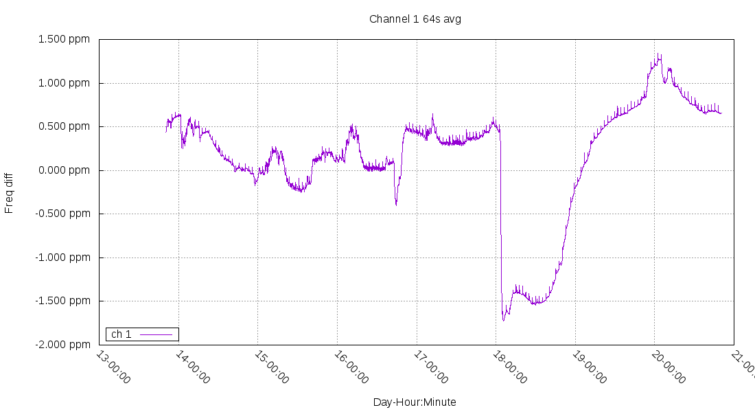
The Raspberry Pi frequency slowed down by roughly 1ppm:
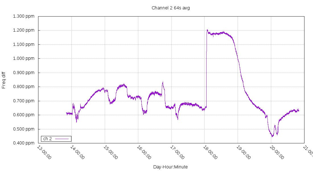
The TCXO devboard frequency sped up by roughly 0.6ppm:
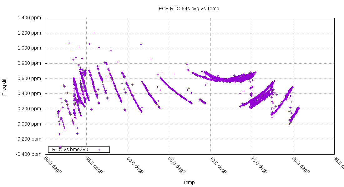
The frequency vs temperature graph for the PCF RTC looks interesting. You can see the curve getting steeper (and compensated in roughly 1.5F steps) as it gets colder.
Quadratic fit
The relationship between temperature and the TCXO's frequency is no longer linear. I've switched from f(x) = a+b*(x-c) to f(x) = a+b*(x-c)+d*(x-c)^2
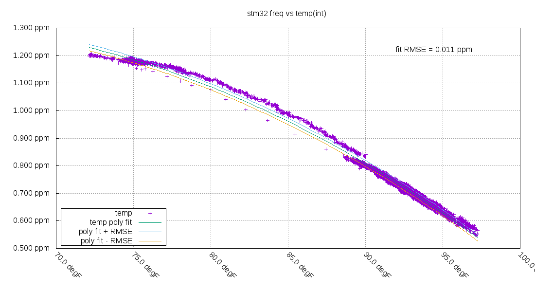
The new fit still has some problems, but the root mean squared error (RMSE) is 11ppb, which is decent.
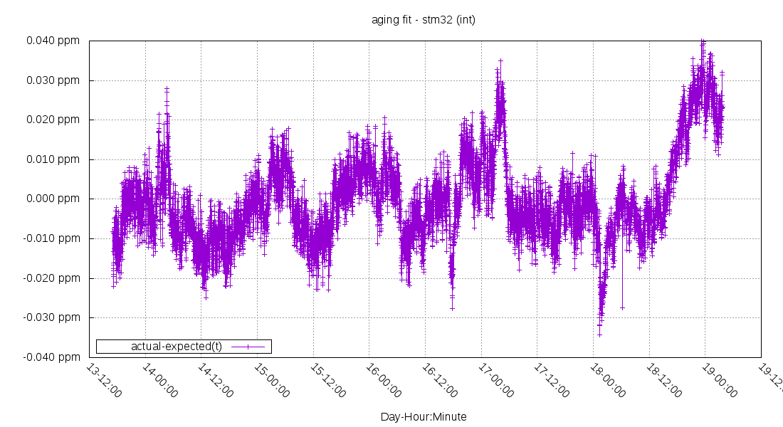
The remaining error after the fit is a much wider range compared to before the cold test.
Further work
Apply the temperature compensation via software and remove the GPS from the board.